Ray Tracing in 20 Minutes
In this post I will explain the basics of ray tracing and show how you can implement a very simple program to render scenes containing spheres, lights and shadows using this algorithm.
Requirements
We will use Python, even though it isn’t the best language for this kind of application, it will serve us very well for learning purposes. We will also need to have two packages: Pygame for opening a window to visualize the final image while it’s still rendering and PyGLM for vector and matrix operations, freeing us of implementing our own math library.
The easiest way to install these two packages is using pip that should be already installed if you have python3 above the version 3.4. You if didn’t have the python installed yet, you can check out this tutorial. Then you only need to run the following command in your terminal:
pip install pygame PyGLM
Now you can test your installation by pasting the following code inside a new file “main.py”:
import pygame
import glm

if __name__=="__main__":
    surface = pygame.display.set_mode((100, 100))
    surface.fill(glm.vec3(0, 0, 0))
    while True:
        for event in pygame.event.get():
            if event.type == pygame.QUIT:
                exit()
        pygame.display.flip()
Run this file and if you see a tiny black window, then everything should be installed correct. You can erase the above code and continue the tutorial.
We start our file importing the packages that we will need. They are the pygame, glm and math, we also import vec3 from glm individually to makes easier to create vec3 objects:
import pygame
import math
import glm
from glm import vec3
Ray
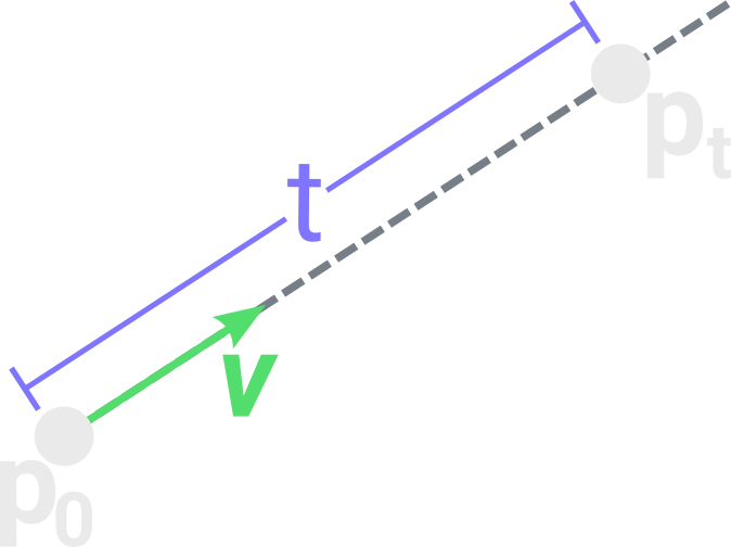
Our first object is the ray, it is essentially a 3D line that will be used to test intersection against other objects. Any point $ P_t $ reached by the ray should be given by the equation:
Where $ P_0 $ is the origin point and $ \vec{v} $ is the direction of the ray. It will be useful to keep $ \vec{v} $ always normalized (with magnitude 1) so the parameter $ t $ is the distance from $ P_0 $ to $ P_t $.
We can implement this simple object with the following class:
class Ray():
    def __init__(self, origin, direction):
        self.origin = origin
        self.direction = glm.normalize(direction)

    def at(self, t):
        return self.origin + t*self.direction
The function glm.normalize will just return the direction vector normalized and the method at is the direct implementation of the equation for $ P_t $
Camera
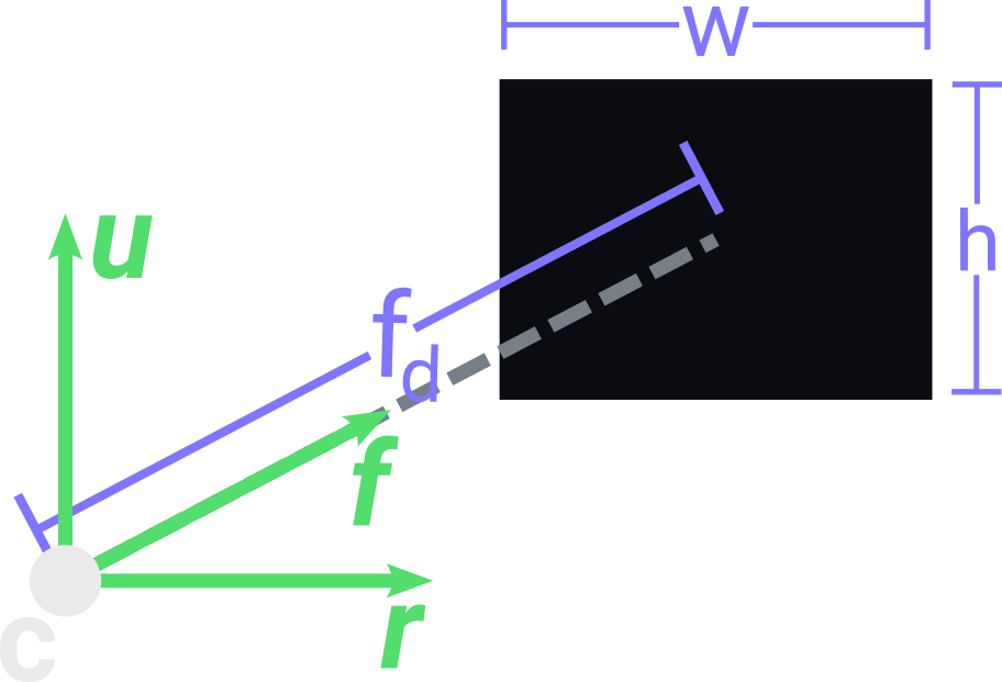
We will use a simple perspective camera that requires only a few parameters: a center point $C$; 3 vectors that give its orientation up $\vec{u}$, right $\vec{r}$ and front $\vec{f}$; a view plane containing a width $ w $ and height $ h $; and a focal length $fd$ that describes the distance from $C$ to the center of the view plane along the axis defined by $\vec{f}$. The following defines our camera class and its constructor:
class Camera():
    def __init__(self, center, euler_angles, width, height, focal_length):
        self.center = center
        self.width  = width
        self.height = height
        self.focal_length = focal_length
Camera Rotation
As we want to rotate our camera, we first need to use some structure to represent this rotation and then apply it to the 3 basis vectors of the camera.
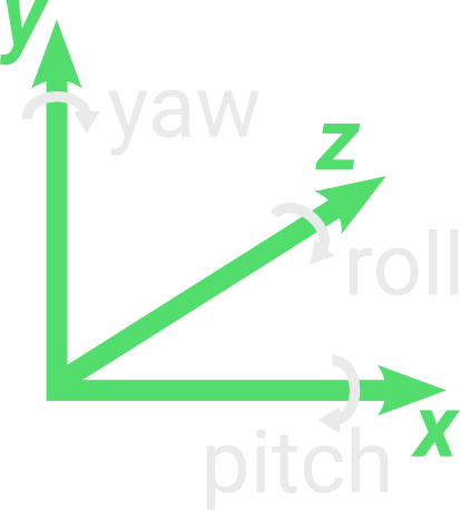
The easiest way to represent a rotation for an object is using Euler Angles, just 3 values, each one describing the rotation of the object along each axis $\vec{x}$, $\vec{y}$ and $\vec{z}$. Given a 3D vector with the value of each rotation in degrees, we can get the three vectors $\vec{r}$, $\vec{u}$ and $\vec{f}$ for our camera like this:
class Camera():
    def __init__(self, center, euler_angles, width, height, focal_length):
        ...
        euler_angles = glm.radians(euler_angles)
        matrix = glm.mat4()
        matrix = glm.rotate(matrix, euler_angles.x, vec3(1, 0, 0))
        matrix = glm.rotate(matrix, euler_angles.y, vec3(0, 1, 0))
        matrix = glm.rotate(matrix, euler_angles.z, vec3(0, 0, 1))
        self.right  = glm.vec4(1, 0, 0, 1) * matrix
        self.up     = glm.vec4(0, 1, 0, 1) * matrix
        self.front  = glm.vec4(0, 0, 1, 1) * matrix
We first need to transform our euler angle vector from degrees to radians using glm.radians. Then we create a matrix 4x4 to store the rotation matrix for our camera. glm.rotate requires an initial matrix, an angle of rotation in radians and the vector defining the axis of rotation that we want to perform. Using this function, we can set up our rotation matrix by concatenating each rotation of our euler angles individually. Finally we get our right, up and front vectors by just applying the rotation matrix to the x, y and z vectors.
Camera View Plane
Our view plane will be divided into a grid, where each squared grid cell (i, j) will be a pixel of our final image. Here is an example of how we could divide the view plane for width 3 and height 2.
![]()
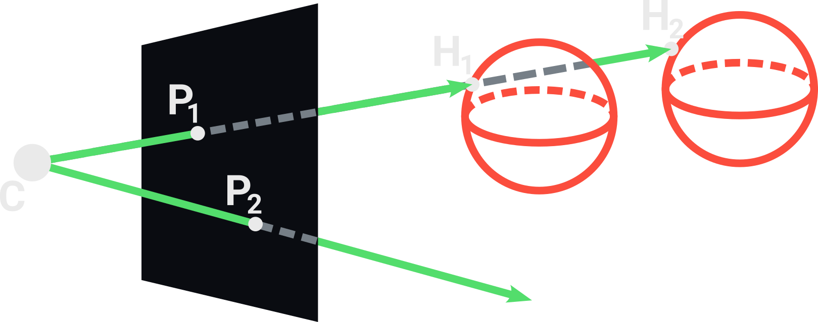
For each one of these pixels we will trace a ray coming from the camera center and passing through the pixel center, then we will evaluate a color for this ray to paint its corresponding pixel in the final image. A simple anti-aliasing approach is tracing more than one ray per pixel and avering their colors.
To create these view rays we first set their origins to be the camera center $C$, then we only need to get a direction vector passing through an arbitrary pixel (i, j) in the view plane. We can divide this direction vector into three components that will be added up together.
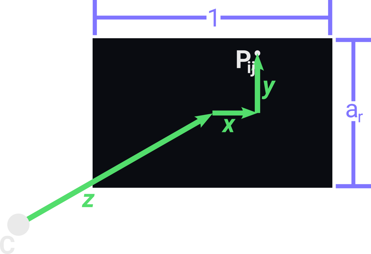
The component $\vec{z}$ is the vector going from the camera center $C$ to the center of the view plane, so we only need to scale the front vector using the camera focal distance.
The component $\vec{x}$ is the vector going from the center of the view plane to the coordinate $i$ of $P_{ij}$ along the axis defined by the right vector. We can get $\vec{x}$ by scaling the right vector with a scalar $x$. First $x$ is $i$ divided by the width $w$ of the view plane, then, as we want our $P_{0j}$ to be on the left border of the view plane, we need to put $x$ between [-0.5 and 0.5] so we subtract 0.5 from $x$.
The component $\vec{y}$ is similar to $\vec{x}$, so it will be the vector going from the center of the view plane to the coordinate $j$ of $P_{ij}$ along the axis defined by the up vector. We can get it similarly by creating $y$ and putting it between [-0.5, 0.5] but we also need to scale it with the aspect ratio $h/w$ of the view plane. This is necessary to ensure that the pixels are distributed in a squared grid.
Finally the direction $\vec{v}$ for a ray passing through a point $P_{ij}$ in the view plane is given by the equation:
The following code is a method of our camera class that creates a ray passing through the pixel $P_{ij}$ by implementing the above equation:
class Camera():
    ...
    def get_ray(self, j, i):
        direction  = self.front * self.focal_length
        direction += self.right*(j/self.width - 0.5)
        direction += self.up*(self.height/self.width)*(i/self.height - 0.5)
        return Ray(self.center, vec3(direction))
Hit
Before tracing our scene, we need to define a class Hit to store data about intersections between rays and objects. In this class we store the hitted object, the intersected point $H$, the surface normal $\vec{n}$ of the object at $H$ and the distance between $H$ and the origin of the ray.
class Hit():
    def __init__(self, object, position, normal, distance):
        self.object   = object
        self.position = position
        self.normal   = normal
        self.distance = distance
Sphere
Now we want to define at least one primitive object to be in our scene, and one of the most simple primitives to define is the Sphere, it only has a center $C_s$ point, a radius $r$ and a color.
class Sphere():
    def __init__(self, center, radius, color):
        self.center = center
        self.radius = radius
        self.color  = color
Then, we need to have a method for testing the intersection between rays and spheres. We can model this problem by merging the equations of the two objects: lines and spheres. if we find the solution of this resulting equation for the parameter $t$, we find the $P_t$ where the ray intersects the sphere. Here is the equation of a sphere:
And here is the equation of a ray where $(x0, y0, z0)$ is its origin point and $\vec{t}$ its direction vector:
Merging them we have this equation:
That expanded becomes:
It’s a quadratic equation so it can have 0, 1 or 2 roots that represent, respectively, the cases where the ray misses the sphere, hits the sphere tangentially and hits the sphere in 2 points. The simplest method for solving this equation is to use the discriminant equation, that can be implemented as the following:
class Sphere():
    ...
    def intersect(self, ray):
        a = glm.dot(ray.direction, ray.direction)
        s0_p0 = ray.origin - self.center
        b = 2.0*glm.dot(ray.direction, s0_p0)
        c = glm.dot(s0_p0, s0_p0) - self.radius**2
        delta = b**2 - 4.0*a*c
        if(delta > 0):
            sqrt_delta = math.sqrt(delta)
            bhaskara = lambda d: (-b + d)/(2.0*a)
            solutions = [bhaskara(sqrt_delta), bhaskara(-sqrt_delta)]
            positive_solutions = [s for s in solutions if s > 0]
            if(len(positive_solutions) > 0):
                distance = min(positive_solutions)
                hit_point = ray.at(distance)
                normal = glm.normalize(hit_point - self.center)
                return Hit(self, hit_point, normal, distance)
        return None
The above code discards negative solutions because the ray can’t intersect any point before its origin. The normal of the sphere at any point $H$ on its surface is just a vector coming from $C_s$ to $H$.
Scene
Our scene will consist of a background color (to paint the pixels of rays that doesn’t intersect any object), an ambient light (to illuminate parts of the scene not reached by any light source) and two lists: one for objects and another for lights. Our scene will provide a method for getting the closest object intersected by a given ray, which the simplest implementation consists of testing the intersection of the ray against all objects in the scene, always keeping a Hit instance for the closest intersected object. If the ray doesn’t intersect any object, we simply return None.
class Scene():
    def __init__(self, background, ambient_light):
        self.background = background
        self.ambient_light = ambient_light
        self.objects = []
        self.lights  = []

    def closest(self, ray):
        closest_hit = None
        for object in self.objects:
            hit = object.intersect(ray)
            if hit and (not closest_hit or hit.distance < closest_hit.distance):
                closest_hit = hit
        return closest_hit

    def trace(self, ray):
        closest_hit = self.closest(ray)
        if closest_hit:
            intensity = self.ambient_light
            return closest_hit.object.color*intensity
        else:
            return self.background
Illumination
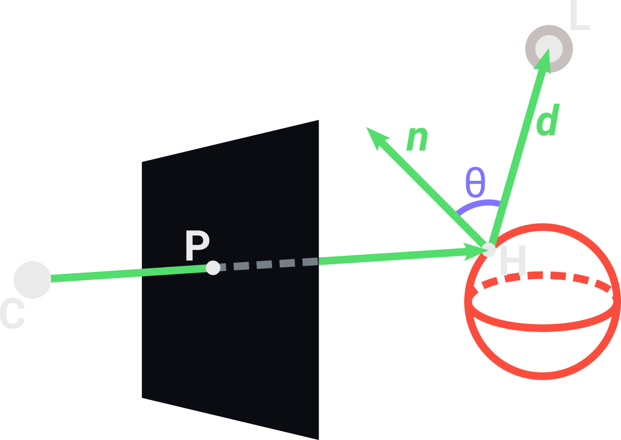
The simplest type of light source is the point light, it only consists of a position and an intensity. Using the diffuse lighting of the Phong model, we make the light more intense depending on the surface normal $\vec{n}$ of the point $H$ that we are interested in calculating the illumination. We first create a vector $\vec{d}$ going from $H$ towards the light position $L$ and get the angle $\theta$ between $\vec{d}$ and $\vec{n}$. As $\theta$ increases, the intensity of the light decreases. Using the cosine of $\theta$, we get a parameter between 0 and 1 that can be used to describe how intense is the light affecting the point $H$. This intensity also decreases with the inverse square of the distance between $H$ and $L$.
class PointLight():
    def __init__(self, position, intensity):
        self.position  = position
        self.intensity = intensity

    def intensity_at(self, hit):
        direction = self.position - hit.position
        distance  = glm.length(direction)
        direction = glm.normalize(direction)
        cos_theta = glm.dot(direction, hit.normal)
        return max(0, self.intensity*cos_theta/distance**2)
The above code uses the property that the dot product of two normalized vector give the cosine of the angle between them to calculates the illumination at a point $H$.
For any point $H$ that we want to calculate the illumination, we can simply add the contribution of each light source in the scene for the total intensity at $H$ and then multiply it by the color of the object at $H$. These sum of all light contributions can be implemented with the following code inside the method trace in the Scene class:
class Scene():
    ...
    def trace(self, ray):
        closest_hit = self.closest(ray)
        if closest_hit:
            intensity = self.ambient_light
            for light in self.lights:
                intensity += light.intensity_at(closest_hit)
            return closest_hit.object.color*min(intensity, 1)
        else:
            return self.background
Shadows
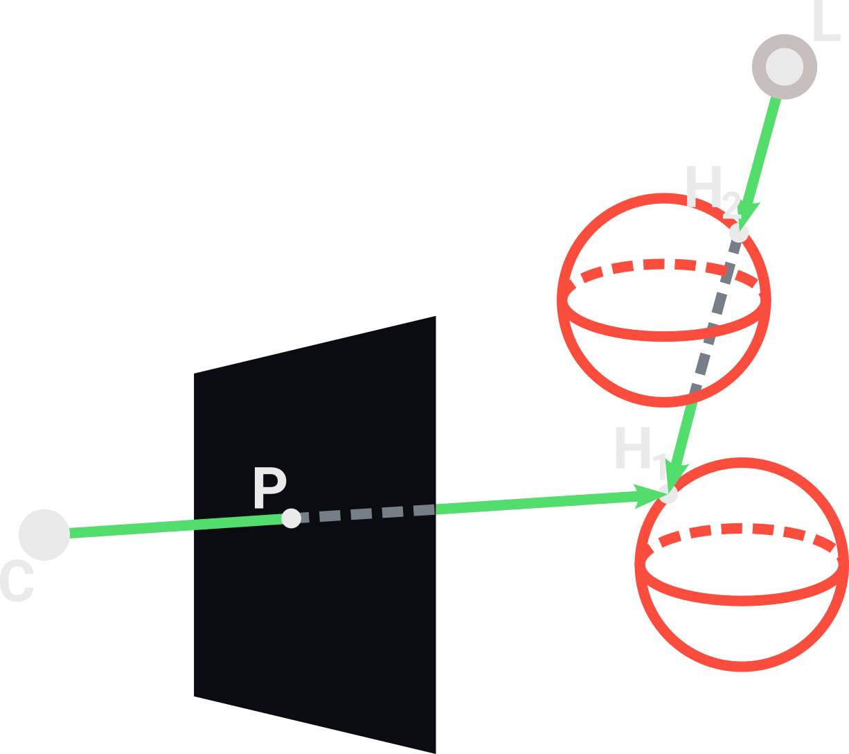
When we are adding up all these light contributions, we also need to know if there is any object between $H$ and a light $L$ being added. The simplest way to verify if $H$ is in shadow is tracing another ray going from $L$ towards $H$. If the first object intersected by this ray is different than the object of $H$, then $H$ is in shadow. In the above image, the point $H_1$ is in shadow because the light ray intersects $H_2$ before $H_1$, removing the contribution of $L$ to the illuminatin of $H_1$. We implement this as following:
class Scene():
    ...
    def trace(self, ray):
        closest_hit = self.closest(ray)
        if closest_hit:
            intensity = self.ambient_light
            for light in self.lights:
                light_ray = Ray(light.position, closest_hit.position - light.position)
                light_hit = self.closest(light_ray)
                if(light_hit and light_hit.object == closest_hit.object):
                    intensity += light.intensity_at(closest_hit)
            return closest_hit.object.color*min(intensity, 1)
        else:
            return self.background
Main loop
Given a scene and a camera, we want to render our image while visualizing it dynamically being rendered. To make this, we first open a pygame window with the dimensions of the view plane and set our initial i coordinate to 0. Then, while the window is open, we iterate over each line i of the image, and for each line we iterate over each column j. For each pixel ij we create a new ray coming from the camera center and passing through it. Then, we trace this ray into the scene and paint the pixel ij with the resulting color.
def render(scene, camera):
    surface = pygame.display.set_mode((camera.width, camera.height))
    surface.fill((125, 125, 125))
    i = 0
    while True:
        for event in pygame.event.get():
            if event.type == pygame.QUIT:
                exit()
        if i < camera.height:
            for j in range(0, camera.width):
                pixel_center = (j + 0.5, camera.height - 0.5 - i)
                color = scene.trace(camera.get_ray(*pixel_center))
                surface.set_at((j, i), color)
            pygame.display.flip()
            i += 1
To get the pixel_center we invert the coordinate i using camera.height - i because pygame treat the line 0 to be on the top of the screen, and we want it to be on the bottom. We also sum 0.5 to both i and j coordinates to get the center of the pixel that we are tracing, and not the bottom left corner.
Creating the Scene
Now, with the render function ready, we only need to create a scene and a camera object. We can fill the list of objects and lights dynamically by creating spheres and lights with random parameters or manually specifying them. Here is an example of a manually created scene:
if __name__=="__main__":
    scene = Scene(vec3(26, 27, 33), 0.12)
    camera = Camera(vec3(0, 5, -8), vec3(-10, 5, 0), 800, 600, 0.8)

    light = PointLight(vec3(-1.3, 8.4, 0), 20)
    scene.lights.append(light)

    sphere1 = Sphere(vec3(2.5, 2.8, 5.15), 2.8, vec3(83, 221, 108))
    scene.objects.append(sphere1)

    sphere2 = Sphere(vec3(0.6, 5.6, 3.6), 0.6, vec3(128, 117, 255))
    scene.objects.append(sphere2)

    sphere3 = Sphere(vec3(-3.1, 1.4, 0.06), 1.4, vec3(128, 117, 255))
    scene.objects.append(sphere3)

    sphere4 = Sphere(vec3(-4.2, 5.4, 4.2), 0.9, vec3(83, 221, 108))
    scene.objects.append(sphere4)

    sphere5 = Sphere(vec3(0, -1000000, 0), 1000000, vec3(234, 234, 234))
    scene.objects.append(sphere5)
In the above code we create an approximated plane using the sphere sphere5 with a very large radius. Finally, we just call the render function passing our scene and camera:
if __name__=="__main__":
    ...
    render(scene, camera)
Resulting in this image:
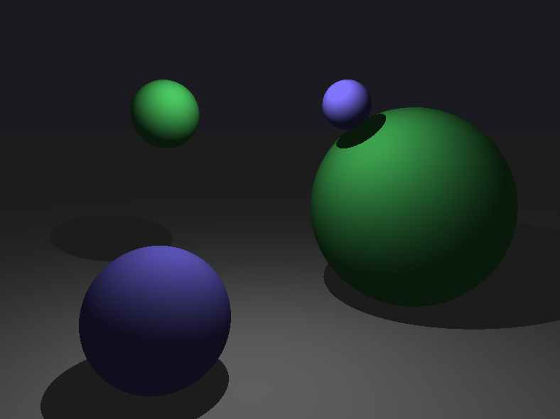
You can check out the full source code for this program here. For any feedback, please contact me at my email: hadryansalles@gmail.com